Repairing an Ampeg V4
I was taking out the trash a few weeks ago and spotted an unlikely item by our dumpster. It turns out that someone had thrown away an Ampeg V4 tube guitar head (my wife now gets me to take out the trash by insinuating that I might find a matching cab)!
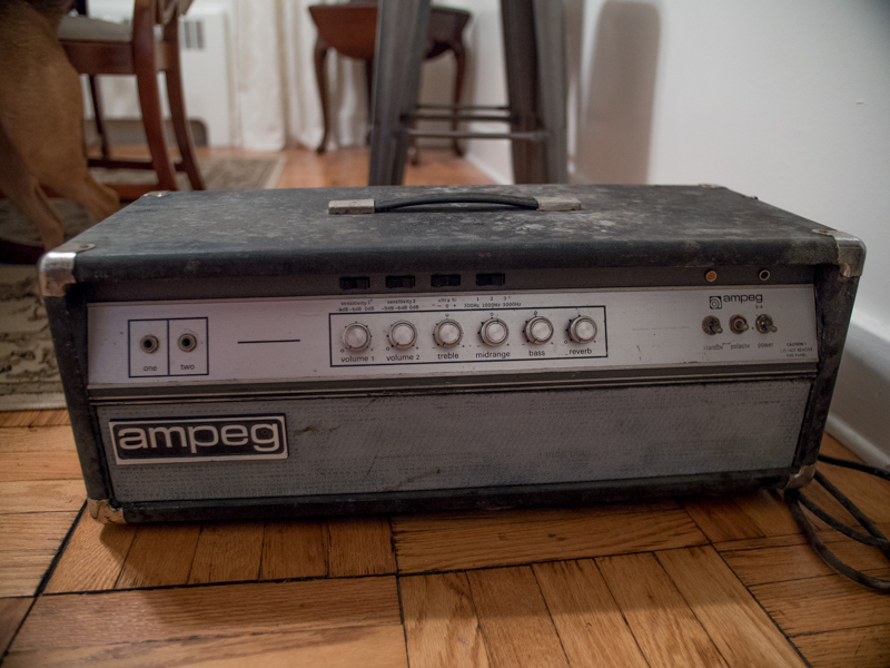
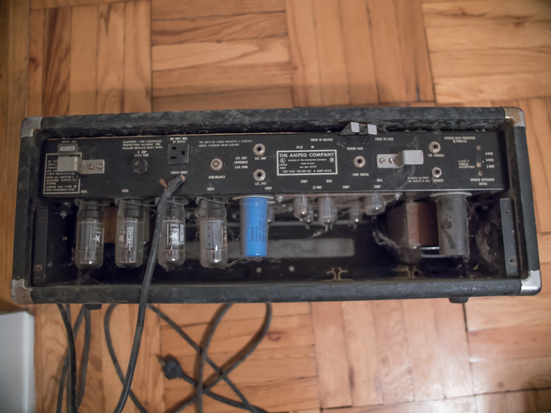
** Warning ** tube amps are very dangerous. Please do not mess around with them if you do not know what you are doing. Large capacitors can hold 100’s of volts even after the amp is turned off.
I immediately went to test it out and it was predictably dead. My first thought was obviously to check the fuse, which tested good. I then did some googling and found a great resource in http://www.ampegv4.com/. This showed me that there is also an internal 10A fuse on V4s. After opening up my amp, I found this fuse was blown. I replaced it with a hardwired short (no need to juggle 2 fuses in testing, although I replaced it with the proper value when I finished). I also made sure to properly ground the amp to prevent the possibility of shock (there are many tutorials you can find online about this, and on this amp involved removing the polarity switch from the circuit removing the infamous ‘death cap’ and connecting the chassis to the ground plug on the power cable).
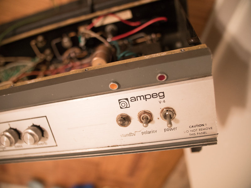
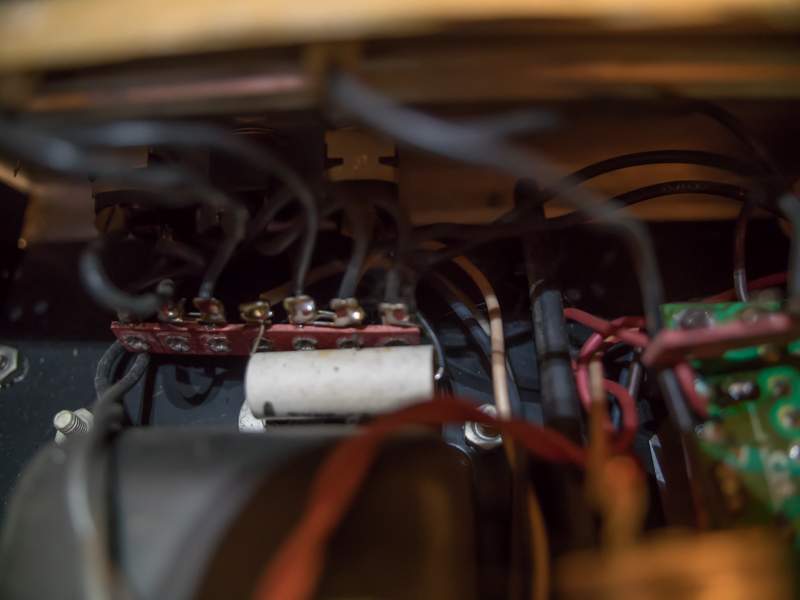
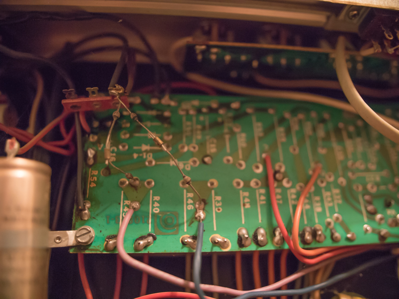
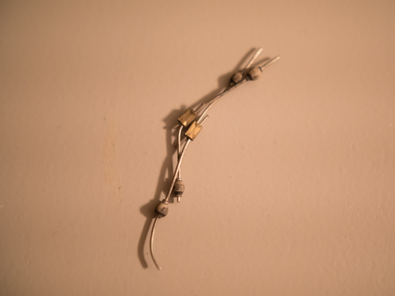
Turning the amp on after this immediately blew the other fuse. So now I had to go searching for a different problem. Searching on the ampegv4.com website showed that a lot of amps have flyback protection diodes that often go bad and can keep an amp from starting. Looking at mine, they were bulging and it was obvious they had gone bad since they were bulging out like balloons. Since they are there for protection, the amp will run fine if they are removed from the circuit, which is what I did. The photo below shows the flyback diodes coming off the circuit board.
After removing the flyback diodes, I was able to get the power light to come on. The tubes also glowed a bright, bright red (not good!) and you could hear a very queit crackling version of the input. The standby light also would not turn on, even when the amp was fully turned on.
A few test points showed that my bias voltage was WAAAY off (actually swinging into positive instead of staying negative when standby was turned off). After testing some of the diodes, I was able to determine the bias diode (D6, you can see it marked in the middle of the circuit board photo above) was bad. I also could see that the resistor for the standby lamp (R54, on the left side of the photo and also fed from the same source as the bias voltage) was burned and bad as well. Replacing these two components was the key to getting the amp working again.
During the troubleshooting process, I did a lot of general cleaning of the circuit boards and solder reflow as a general troubleshooting method hoping something would magically work. All of that was ok and didn’t hurt anything, but the most helpful troubleshooting technique was isolating my problem to specific parts of the circuit, testing components and replacing anything found to be bad.
The Amp is now cleaned up and works great, although living in an apartment doesn’t give me many chances to really crank the volume like it deserves!